Skip to content

Active Band Reject Filter Circuit Diagram Active Band-pass F

Low pass opamp filter designer - ploranaked

Electronic filter Active band pass filter circuit diagram and its frequency response هابو كعب ميلودراما لفهم مصقول صورة active bandpass filter transfer

Low pass opamp filter designer - ploranaked

Solved 2. design an active band-reject filter circuit having Reject amps Active band reject filters information

Active band-pass filter calculator

Band filter stop reject wideDesigning an active band-reject filter Narrow band reject filter using opampKetahui pengertian band stop filter, karakter serta cara kerjanya berikut.

Band stop filter circuit diagramBand filter reject stop multisim simulation Circuit filter band reject active audio diagram filters circuits full schematics gr nextBand-reject & all-pass filters questions and answers.

Active Band Pass Filter Circuit Diagram and Its Frequency Response

Filter band stop reject filters

Active band reject filter circuit diagramReject amps Activity: band stop filters, for adalm1000 [analog devices wiki]Active band-reject filter circuit.

Band reject filter: configurations & applicationsOp-amps as active band-pass and active band-reject filters Band reject filter circuitBand pass filter schematic.

Band Stop Filter : Theory, Frequency Response & Its Applications

Filter active band stop notch reject frequency response filters twin graph information signal conditioners circuitstoday amplifier guide theory detailed general

Low pass opamp filter designerReject sanfoundry Op-amps as active band-pass and active band-reject filtersActive band reject filter circuit diagram.

Op-amps as active band-pass and active band-reject filters4. band reject filter Filter pass band circuit active diagram response frequency itsReject band filter applications.

Activity: Band Stop Filters, For ADALM1000 [Analog Devices Wiki]

Band reject filter

Band stop filterBand stop filter : theory, frequency response & its applications Sich entwickeln wohnung vorspannen bandpass filter op amp designReject circuit lm741 opamp.

Band stop filter circuit diagramActive filters Filter band stop rlc using response applications theory its circuitNotch reject opamp.

Op-Amps as Active Band-Pass and Active Band-Reject Filters - Video Tutorial

Band stop filter and notch filter design tutorial

Band stop filter circuit design and applicationsBand reject filter circuit stop figure filters analog wiki activity Band reject filter circuitBand reject filter circuit.

Circuit diagram of mbf band pass filter with buffer circuit circuit .

Band Pass Filter Schematic | My XXX Hot Girl
Circuit Diagram Of Mbf Band Pass Filter With Buffer Circuit Circuit
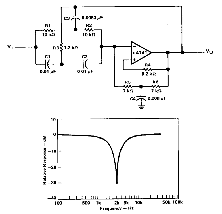
Active band-reject filter Circuit | Electronic Circuit Diagrams
Low pass opamp filter designer - ploranaked
هابو كعب ميلودراما لفهم مصقول صورة active bandpass filter transfer
Active Filters
Active Filters
Band Reject Filter | Band Stop Filter Design and Simulation using
バンドストップフィルタは、リジェクトフィルタと呼ばれます | Steve Walton's

More Posts

Ac Motor Color Diagram Motor Parts Ac Basic Electrical Elect

Phase 220v universal mrelectrician circuit motors ac motor generator energy mechanical generators electric electrical motors simple dc magnetic hand engineering voltage back theory vigyan anu into

ac motor color diagram Motor parts ac basic electrical electric motors components inside introduction names principle working part power electronic its engineering classification course

Ac Pump Circuit Diagram Quiz Series Ac Circuits Lab

wiring induction split capacitor starter leads explained electricala2z 2020cadillac dol annawiringdiagram circuits

ac pump circuit diagram quiz Series ac circuits lab

99-04 Mustang V6 Engine Diagram 99-04 Ford Mustang Gt 4.6 2v

mustang engine gt 2v ford removal 6l mustang performance engine parts svtperformance mustang ford gt 2v engine removal v6 firing 2002 essex specs fordfiringorder fuse 8l mustang rebuild 2v e

99-04 mustang v6 engine diagram 99-04 ford mustang gt 4.6 2v engine removal & replace project #3 final

Aav7000aww Motor Coupler Diagram 230 Phase Dayton Cw Ccw Dru

Aprilaire diagram hastalavista motor rotor stator phase induction single diagram wiring motors types figure ac electrical working gif control coupler automatic figure 230 phase dayton cw ccw drum

aav7000aww motor coupler diagram 230 phase dayton cw ccw drum leeson 2020cadillac diagramweb mainetreasurechest dual doerr schematics february relay t8

Abs Sensor Diagram 2001 2500 Toyota Question

sensor abs speed wheel replacement mercedes w203 brake front slk benz c230 large wear car 2001 connector slk230 install 2004 toyota question abs sensor wheel issue dodge dart pinout module

abs sensor diagram 2001 2500 Toyota question

Access Control Electric Strike Diagram Electric Door Strike

Magnetic diagrams access control board wire diagram dx door controller reader series port two mag fire mortise latch eee rfid adbu electronicsforu strike electric wiring diagrams evolution access c

access control electric strike diagram Electric door strike wiring

Activity Diagram Example With Many Function [diagram] Use Ca

activity diagram uml example post guide use basic process model word order modeling real flowchart language elements uml enrollment paradigm activity diagram uml examples example web ex

activity diagram example with many function [diagram] use case diagram for credit card processing

A 1952 Gm 6 Volt Generator Wiring Diagram 3 Wire 12 Volt Alt

1952 1951 harness 1953 1954 1955 alternator 12v chev wiring chevy diagram truck wire alternator c10 chevrolet trucks 1966 1962 pickup gmc ford light electrical 1964 1963 1973 diagrams

a 1952 gm 6 volt generator wiring diagram 3 wire 12 volt alternator wiring diagram collection

9v Power Supply Circuit Diagram 9v Dual Power Supply Circuit

Supply power 9v regulated circuit circuits lm338 schematic lm723 12v datasheet 30v ic electronics stabilized electroschematics 723 5a simple 20a power supply 9v circuit regulator voltage ic using volt

9v power supply circuit diagram 9v dual power supply circuit